Reincarnation: 1uzfe reanimates 4runner with impending flatline

The 1UZFE EGR Delete Kit is available for sale here.
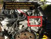
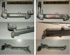
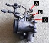
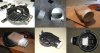
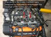
PRE-CONVERSION WORK ON ENGINE: Plenum Bolts and Studs​

Four studs (two long on one side and two short on the other) on the intake manifold were removed and swapped to the opposite side so that when the plenum was replaced on top it could be bolted down properly with no potential for air leaks between plenum and intake manifold.
 

Attachments

  • 1uzfe plenum reversal.jpg
    1uzfe plenum reversal.jpg
    127 KB · Views: 17
Last edited:
Have a read up on how to make the temperature gauge more accurate.

From the factory Toyota gauges don't start to move past halfway until at least 99degC, and even then some models (engine specific) don't reach red until about 110degC.

I read up on a quick mod someone did that makes the gauge move past half way at about 97degC, and into the red just over 100degC, which is what you want.

btw, the 1UZ and the original gauge temp sensors would be the same electronically.
 
Peewee: that is VERY interesting. Why would Toyota do this? It seems a bit irresponsible as many would assume that the red zone would equal about 100degC and not 110degC.

I found an article on the Toyota Surf forum regarding this after reading your post. Will probably end up doing this at some stage but FTM I have just bought an after market gauge to keep an eye on things.

The Surf info is here:
http://www.toyotasurf.asn.au/forum/viewtopic.php?t=14717&
 
PRE-CONVERSION WORK ON ENGINE: Idle Speed Controller (ISC) Inlet Hose​

The ISC (normally at the front of the plenum) is now at the rear of the plenum due to the plenum reverse. The ISC inlet hose was plumbed to the large nozzle under the throat of the throttle so that the air/LPgas mixture is still drawn in during idle.

The ISC hose also rubbed on the metal heater hose tube that runs from the front of the engine near the water pump and beneath the intake manifold to the back of the engine. This metal hose had to be bent slightly by the mechanics so that the ISC hose and heater hose did not clash.
 

Attachments

  • ISC inlet and heater hose.jpg
    ISC inlet and heater hose.jpg
    140.6 KB · Views: 20
Last edited:
PRE-CONVERSION WORK ON ENGINE: ISC and Throttle Coolant Line Modification​

I deleted the coolant line that runs from the front of the engine through the throttle and then through the ISC. When I turned the plenum around 180 degrees part of the coolant inlet on the bottom of the ISC fouled against the plastic loom cover at the rear of the engine. The purpose for this coolant pass through on the ISC is apparently keeping it warm and from freezing in colder climates. Since I am in sunny Australia I decided to delete it from the cooling system. Both the ISC and throttle was deleted. The part that was fouling on the engine cover was ground off.

This coolant line began at the front of the engine on the coolant crossover pipe and ended at the back of the engine on a nozzle sticking out of the rear coolant crossover pipe between the heads. Which brings me to my next step…
 

Attachments

  • Grind off water inlet 01.jpg
    Grind off water inlet 01.jpg
    141 KB · Views: 18
Last edited:
PRE- CONVERSION WORK ON ENGINE: Rear coolant crossover pipe mod​

As mentioned there is a coolant line that runs from the front of the engine near the water pump, through the ISC and the throttle then re-enters the cooling system on the rear crossover pipe. When the engine was installed this nozzle bumped against the hand brake bracket on the fire wall.

Because I had deleted the throttle and ISC lines from the cooling system I did not need the nozzle on the rear coolant crossover pipe. I had it cut off completely and the hole was tig welded over. This created a little more room around the rear of the engine. This, in a 1UZ to 4runner swap where you are fighting for millimetres, is a huge gap. The result is greater clearance, no more vibrations. The pictures show what nozzle I am talking about and how much room cutting this thing off creates.
 

Attachments

  • Coolant Crossover pipe.jpg
    Coolant Crossover pipe.jpg
    82.5 KB · Views: 15
  • Coolant Crossover pipe (rear) - cutting and tig welding.jpg
    Coolant Crossover pipe (rear) - cutting and tig welding.jpg
    108.8 KB · Views: 17
Last edited:
Peewee: that is VERY interesting. Why would Toyota do this? It seems a bit irresponsible as many would assume that the red zone would equal about 100degC and not 110degC.

I found an article on the Toyota Surf forum regarding this after reading your post. Will probably end up doing this at some stage but FTM I have just bought an after market gauge to keep an eye on things.

The Surf info is here:
http://www.toyotasurf.asn.au/forum/viewtopic.php?t=14717&
Yep, thats the one I found.

Toyota do it to stop people from coming into the dealership saying the temp is going past half way (ie, people think its getting hot).
Toyota obviously decided that 100degC is still in the acceptable region for that motor (I'm pretty sure all gauges are slightly different in this region).
I know my Cressida RAPIDLY wen't from normal to hot when it got over 100degC.
 
I guess it is easier to fool customers than educate them! A decent after market gauge is probably the only way to know for sure.
 
PRE-CONVERSION WORK ON ENGINE: Throttle and throttle cables​

The whole point of the plenum reverse was to swap the throttle from the drivers (right) side to the passengers (left) side so it would sit neatly in line with the snorkel and LPG setup. After some careful reading on various forums the original (Toyota Celsior) Throttle was replaced with an early 1990s US/ left hand drive Toyota soarer SC400 throttle.

I bought the US SC400 throttle from Ebay/the states. This early throttle does not have the extra trac-control butterfly in the throat so it is simpler, and most importantly, because it is from a left hand drive car it has the cables pulling from the opposite side. The advantage of this is so when you reverse the plenum like I have they pull from the driver’s side on a right handed vehicle (hope this makes sense). This created minimal or no alterations to the accelerator cable positions already existing on the v6 4runner. The transmission cable was taken off a LN automatic Hilux and installed by the mechanics and seems to fit with no problems.

There is also a big tube/nozzle at the bottom of the SC400 throttle that normally goes to the valve cover. It is situated just forward of the butterfly. This is now the air input for the ISC, as shown in post #44. The tube on the (original) celsior throttle was very small whereas on the SC400 it was much larger. The benefit of this was two-fold in that not only was it the same size as the ISC inlet but it drew air and LPG from exactly the right spot: that is between the LPG mixer and the throttle butterfly. I therefore did not have to tap a fitting in between the two that goes to the ISC. Hope I explained this OK.
 

Attachments

  • Throttle setups 01.jpg
    Throttle setups 01.jpg
    155 KB · Views: 18
  • Throttle tubes 01.jpg
    Throttle tubes 01.jpg
    83.4 KB · Views: 16
Last edited:
PRE-CONVERSION WORK ON ENGINE: Plenum Vacuum Hoses​

Due to plenum reverse many of the air hoses had to be re routed.

• The crank case vent hoses go from valve covers to a T-junction and then to a home made kitchen sink catch can. These then go into the plenum to comply with local emissions laws. There is a tube now on the front of the plenum (that used to go to the brake booster) that this connects to.

• A hose goes from a nozzle on the side of the plenum (that used to go to the PCV nozzle on the valve cover) to the brake booster cylinder.

• A small vacuum hose from the top of the throttle goes to the fuel regulator.

• A small vacuum hose goes to the Charcoal canister from a little box near the fuel regulator towards the rear of the plenum.

• The large Idle Speed Control (ISC) hose (now on the back of the plenum due to plenum reverse) takes air (and LPG gas) from the intake tube between the gas mixer and throttle. This is so it can idle when running on gas. (see previous post for more details)

• Another small hose should go to/from the power steering for an idle up when the steering is on lock but this was not installed and there does not seem to be any ill effects.

• All other holes were plugged up or deleted.
 
PRE-CONVERSION WORK ON ENGINE: PCV Valve​

Had to install new PCV valve grommet in the valve cover as the old one was hard and it cracked too easily when I removed it from the valve cover for the powder coating. In Australia this is part number 90480–18001 and should be $6.95 from the Toyota stealership. As always with Toyota, best to call them first and make sure they have one. I had to drive across the city to get it.
 
The original gbox Celsior cable is backwards in that picture.
They go in opposite directions. (Not sure it matters, just thought I'd point it out)
 
Hey Peewee, now I am all confused. I just took a picture of the Celsior throttle and there appears to be THREE cables, two pulling right and one pulling left. I am pretty sure my motor did not come with trac control so what could the third one be?

In the picture I have given them letters, A, B and C. Is the below format correct? What is B?

A: Accelerator peddle cable
B: (unknown)
C: Transmission cable
 

Attachments

  • Celsior Throttle 01.jpg
    Celsior Throttle 01.jpg
    128.9 KB · Views: 11
Last edited:
DOH!!!!! :banghead: :banghead: :banghead: :banghead:

Thanxs Smitherz! I picked the wrong week to start sniffing glue....
 
No prob. Before long you'll know every nut and bolt on that engine! That reminds me that I need to keep my eyes peeled for a cruise control kit for my swap. =]
 
PRE-CONVERSION WORK ON ENGINE: Temporary Air Box and Intake​

For the purposes of getting it in and out of the mechanics I made a temporary air box from the original V6 one to fit the new AFM. This was later replaced once the LPG mixer was installed, and is only really mentioned here for historical purposes.

I tried to make sure that all piping on the air intake was no less than 80mm in diameter, which is the diameter of the throttle intake. I pulled off the original AFM and adapted the top of the air box so that it had a circular outlet that was 80mm in diameter. This was not easy as any significant increase in height would smack against the bonnet. I cut up several pieces of PVC downpipe plumbing and covered it in fibreglass for strength. This was going to be a TEMPORARY arrangement anyway until the engine was in. I could then try to rig up a proper one. Sorry about the crap pictures.
 

Attachments

  • DSCF4979.JPG
    DSCF4979.JPG
    183.7 KB · Views: 15
Last edited:
This is where the pre-conversion work on the actual engine ended, but the fun did not stop there. The steering, gearbox and transfer case still needed some major work done to them before the engine was anywhere near ready to be transplanted into the anxious donor patient.
 
Last edited:
PRE-CONVERSION WORK ON VEHICLE: Steering Damper Bracket Issues​

For this type of swap the steering damper MUST be relocated as it slices into the oil sump if it is not moved. There is no way around it unless you want the engine to be sticking out of the bonnet by about half a foot.

Luckily Rancho make a steering damper relocator kit (steering damper and damper relocator kit product numbers are RS5402 and 5573 respectively) so this step was very easy. The relocate kit is a direct bolt on to existing bolts and holes. You may have to cut the steering damper knuckle on the drag link though so it won’t smash into the pan.
 

Attachments

  • Stering stabilizer Rancho relocation kit2.jpg
    Stering stabilizer Rancho relocation kit2.jpg
    121.8 KB · Views: 26
Last edited:


Back
Top