Many people who install the Crown engine without the automatic transmission chose to wire the engine to the car themselves.
To make this a little more accessible for all I’ve taken my experience from wiring and then re-wiring my own car, combined it with “KDog’s” excellent wiring Diagrams and some great freehand drawing supplied by “thegianttomato” plus numerous threads and posts of this and other Sites and distilled it into what I hope is a simple and easily followed set of instructions that will give you the satisfaction of “doing it yourself”. Lastly I need to thank 34FORD for the excellent Visio presentation schematic of what we are doing here.
To make the engine run requires the connection of around 12 wires. It’s that simple.
If you haven’t done automotive wiring before have a surf of the Net and learn what you can. You don’t need to be an electronics engineer but if you can solder and understand how the current flows plus the use of relays you are well on your way.
You need the following tools:
- Wire cutters.
- Soldering iron and solder I use a gas powered “Portasol” as it heats quickly and isn’t connected to the wall by a cable so I can get into tight spots (like under a dashboard) without getting wrapped up in the cable..
- Heat shrink tube in small and medium sizes.
- A multimeter (and the ability to use it) that will read volts DC and continuity. It doesn’t have to be expensive. You will only be looking to read 12volts DC and test for continuity. Try this site if you need helphttp://www.wisegeek.com/what-is-a-multimeter.htm?referrer=adwords_campaign=multimeter_ad=010091
- A good crimping tool and a variety of spade and loop terminals.
- Spare wire of the appropriate colours (see later) this can come out of the loom in your half cut or any old loom if you don’t have a half cut.
- Screwdrivers and the usual spanners you have in your tool box.
- Electrical tape in two colours. But can be replaced with a marker pen.
- A permanent marker for writing on your alloy panel
Parts you will need:
- 4 x 12volt relays (don’t use the Toyota ones there’s no way to mount them, their expensive and hard to find replacements for) or 3 if you use a single speed fuel pump.
- I fuse panel. I recommend provision for at least 8 fuses in the panel. Use spade type fuses as they are easier to work with.
- I aluminium panel big enough to fit the relays, fuses and ECU. I used a panel around 250mm (10”) by 300mm (12”)This panel allows you to keep it all neat so you can understand it all later.
- 1 x 8 way male/female connector.
- 1 x 6 way male/female connector
Other required items:
- Pen and paper. You can’t make too many notes when doing this. You can always refer to your notes later if needed.
- The workshop manual for your car or at least the wiring diagram.
- A good supply of re-hydration fluid. Usually in cans and/or longnecks. Soldering can be hot work!
Some advice:
When extending wiring always try to use the same coloured wire. If you can’t get a perfect colour match, try and get as close a match as possible. Always be careful you don’t use a colour that is already in the loom you are working with. There’s nothing worse than following a blue wire that turns into a red wire somewhere inside a loom or out of sight. Make the effort when carrying out the wiring as it will save you an enormous amount of work later.
It’s worth having a look at the diagrams KDog produced and posted on the Lextreme forums. print off the appropriate pages. If wiring with the ECT the pages there will make it easier. Once you have the engine wired the transmission will be easier as you’ll have proven to yourself it’s easier than it looks.
Let’s do it!
Step 1.
Ensure the battery is disconnected before doing any work on the cars electrical system.
Step 2.
Number the plugs on the ECU (with your marker pan) as follows:
- largest plug on the ECU and has 26 pins
- second largest on the ECU with 22 pins
- smallest plug of the 3 in a row. It has 16 pins
- the 8 pin plug attached to a bracket away from the other plugs
Step 3.
Once you’ve removed the loom and ECU and ECT from the car you need to separate the ECU from The ECT. First step is to put one colour of electrical tape on the ECT plugs and another on the ECU plugs. This will save getting confused when working with them. You could just write ECU and ECT on the plugs with a marker pen and not use any electrical tape at all. This is a sign of quality work. NOTE: If you’re keeping the Auto don’t cut any wires.
To separate the ECU/ECT cut all wires connecting the ECT to the ECU. Perusal of KDog’s table tells us the wire colours are:
ECU Plug 1
- Yellow/Green
- Yellow/Red
- Yellow
- Pink/Green
- Pink Black
ECU Plug 2
- Red
- Red/Black
- Red/White
- Brown/White
- White/Violet
- Violet
ECU Plug 3
- Blue White
ECU Plug 4
- Blue/White
The best thing here is to look carefully before cutting as similar wire colours appear elsewhere on the ECU. Check they join the ECU plugs to the ECT plugs. When cutting the wires try to get as close to the plug as possible and fold the wire back into the plug to stop it shorting with another cut wire.
With Plug number 4 an ooption is to open the ECU and cut the wires off the board and remove the wires and plug for convenience. I retained the black rubber gasket and filled the holes in it with some black sealant to keep dirt etc out.
Step 4.
Next be brave and cut all wires leading into the fuse box. The Toyota box won’t be used so cut the wires close to the plugs.
Once you’ve done this you can separate the transmissions wiring from the engine loom all the way back to the transmission. You can discard them. It’s a bit fiddly but worth doing as you will have fewer wires to fight with.
Step 5.
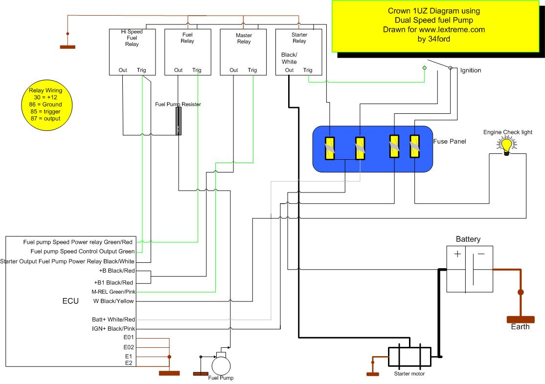
I wired my car with the twin speed fuel pump so follow these instructions if that is the way you want to go. If you are happy with a single hi-speed fuel pump I will show the different steps at the end of this document plus some advantages/disadvantages of both options.
Position your 4 relays, fuse board and ECU on your alloy panel. Make sure they’re far enough apart to access them easily and have plenty of room to work around them. One thing to bear in mind is try to locate the ECU so the existing engine loom will reach it without having to unplug it every time you want to work around it. I have to unplug the plugs 1 & 2 on mine and it’s a PITA!
Step 6.
Wiring the relays for power.
I started wiring with running permanent 12volts (connected directly to the battery through a fuse) to each relay. I did this by using short pieces of the same coloured wire and crimped two pieces of wire (after soldering them together) in each terminal. If you don’t know the correct way to solder try this linkhttp://www.aaroncake.net/electronics/solder.htm I ended up with a short “daisy chain” of terminals. That’s your first (hopefully) successful soldering task. When you do this try and keep the wiring neat. I used wire ties to temporarily hold the wires neatly. A short length of discard fuse wire is simple sand easy to twist and untwist. I used cable ties after everything was finished for a permanent job. After this I ran an earth for each relay. I did this the same way as the power cable and tied them to the power cable. I “earthed” the earths to the alloy panel using a loop terminal swagged to the end and bolted to the panel.
Step 7.
Wiring the ECU to the fuse board and relays.
- The first ECU wire I connected was the 12 volt battery connection. This goes to the permanent hot terminal of the fuse board. Remember the power must go through the fuse to protect the car from a fault in the ECU. This is the White/Red wire from ECU plug 2. When fitting all wires try to lay them out so the finished length allows them to form a neat little loom.
- The next wire I installed was the 12 volt ignition wire. Coloured Black/Pink. This goes to the fuse board terminal controlled by the ignition switch.
- The next wire I installed was the trigger wire for the Master relay. At this point write above the relay “Master” and run the Green/Pink wire to the trigger terminal on the relay. Again lay it out nicely and tie it into your little loom. Note: there’s no special order for the mounting of the relays.
- The next wire was actually 2 wires. I ran the Black/Red “Power from Power Relay” wires. Connect them to the Master Relays output.
- The next wire the Green/red “Fuel Pump Power Relay” wire. This went to the second relay. Write Low Speed Fuel pump above it.
- The next wire was the Green wire “Fuel pump Speed Control Output” which went to the trigger terminal on the third relay. Before doing this read point 7. Write Hi-Speed Fuel Pump above this relay.
- The Black/White “Starter Output to High Speed Fuel Pump Power Relay” is next. This shares the same spade terminal as the Green wire above. Both wires go to the trigger terminal of the hi-speed pump relay.
- The last wire from Plug 2 is the Black/Yellow “Engine check light” wire. This wire runs to a light on the dash which is in turn connected to 12volts controlled by the ignition switch. To get it there it should run through the 8 way plug connector you purchased. For the time being run it into the plug, with a spade terminal supplied with the plug, and we will get to the other side of the plug later.
- Looking at Plug 1 of the ECU we notice it has 3 brown earth wires. They need to be run to a good clean earth. It may be best to drill a hole and fasten them to your alloy panel. Use a loop terminal to do this. You will need to earth the alloy panel later. My panel is attached to the car with a brass hinge so doesn’t need an earth. Being able to hinge the panel makes working on it later more bearable.
ECU Plug 3
This plug also has an earth that requires inclusion with the above earths.
That has the ECU wired to the relays and fuse panel.
Step 8.
Wiring the Relays to the car.
Run all the following wires through the 6 way connector for ease of removal.
- First wire is an earth from the panel through the 6 pin connector to a good clean earth. Don’t use a self tapping screw. Use a bolt and clean the metal under it. Better still use a “star” washer between the earth lead and the body. This will ensure a good connection. Try and use a mid sized Brown wire (to keep in the colour code) as it needs to carry a fair load.
- Run a wire (any colour you like but one that matches your vehicles wiring would be smart) from the output terminal of the low-speed fuel pump relay to one side (any side it doesn’t matter) of the Fuel Pump Speed Resistor, the large silver device about 80mm x 50mm x 20mm, that was mounted in front of the fuse box in your half cut. You were wondering what that was, weren’t you.
- Run another wire from the high-speed relay, again colour isn’t critical (but something that ties with the fuel pump feed would help), to the Fuel Pump Speed Resistor, don’t terminate it yet. Now connect the cars old power feed for the fuel pump to this last wire and terminate and connect to the opposite side of the Fuel Pump Speed relay to the low-speed fuel pump relay connection.. The cars power feed should now be connected to the output side of the resistor with your new wire. What we have done here is feed the low-speed pump power through the resistor to drop the voltage. When the high-speed relay trips it by-passes the resistor and give the fuel pump the full 12 volts. One point to keep in mind; if you use a lift pump from your fuel tank to a swirl pot you may need to feed this pump 12volts all the time.
- Last relay is the starter relay. The output of this relay goes to the heavy black wire in the engine loom where it was cut off the fuse board or plugs. This is the solenoid trip wire so it’s quite heavy. You can’t access the other end of this wire as it’s under the manifold. This is one of two black wires in the loom. The other wire is a small black wire that is the tacho feed. You can test the continuity of this wire (to identify it) by probing the 5th wire on one of the two igniter plugs. One plug has 4 wires the other 5. It’s the centre wire. If you have continuity you’ve found the tacho wire. Whilst talking of igniters don’t forget they also need to be earthed to work.
- You need to connect the starter solenoid trip wire from your ignition switch to the trip terminal on the starter relay. Again run it through the connector.
That’s the relays wired.
Step 9.
The rest of the Loom
We now need to wire the rest of the engine loom to the car. REMEMBER you need to run these wires through the 8 pin connector or your wiring loom will be permanently attached to your car.
- Since you probably have found the Tacho wire whilst doing the starter feed you may as well get it out of the way now. This wire joins the Tacho sensing wire in your car. Strip the end of the black wire and the cars sensing wire. Slide a 20mm length of heat shrink up one of the wires. Try to keep it at least 100mm (4”) away from the joint or it will shrink before you get to use it. No man needs that problem! Slide the loose ends of the exposed wires together so they pass through one and other. The length of exposed wire doesn’t need to be any longer than 10mm Give it a slight twist and it should hold together. Solder the joint. Once the joint has cooled (20 seconds is ample) slide the heat shrink over the joint and hold the soldering iron very close to the heat shrink and it will shrink (strange that) to a tight fit over the joint. .
- The next wire from the loom is the oil pressure warning light. This wire is Yellow/Black and it joins to the oil light in the cars wiring just like the tacho feed.
- Next is the temp gauge. This is the Yellow/Green wire and it connects to your temp gauge sensor just like the oil light.
- Next is the air conditioning compressor clutch feed. This wire is Black with a Blue stripe and connects to the cars feed like the above wires.
- Next is Charge light. This feed needs to go through the 6 pin connector and to your fuse board. It needs to go to a 7.5 amp fuse that is powered when the ignition is on.
- From the 8 way connector (not the 6) you need to run your engine check light (remember the Black/Yellow wire). This goes from the connector to a spare dash light (or a special light/LED you’ve installed and back to the fuse board. This light needs power when the ignition is on. Run it back through the 8 pin connector to your fuse board and pick up switched 12volts there.
NOTE
All wires running from the ECU to the car (not the relays or fuse board) must go through the 8 connector plug otherwise you will have to disconnect/cut all the wiring to get the engine out. No fun!
Step 10.
Final inspection/Starting
At this point you are ready to do a little checking and tidying up.
First check and double check your connections and that the wires go to the right places. The best way is to go through the above instructions in the order they are written. Tick them off to confirm that a) you have checked them and b) they go to the right place.
Once you are satisfied all is in order you can re-connect the battery and see what happens.
Don’t expect any smoke. Not if you have it right. The ECU is well protected against incorrect polarity so don’t be paranoid.
Using your multimeter do the following checks:
- Check for power at the fuse board for the permanent (direct to battery) power. If you have that turn on the ignition.
- Do you have power on the fuse board for the 12volt ignition controlled power? Yes? Move on. Now check you have the fuse board fed with the right lead from your cars ignition. Be aware some cars use a “Eureka” resistance wire when running that reduces the 12volts to 6volts to run a 6volt coil. They put 12 volts across the coil when starting to give a fatter spark. So make sure you have the full 12volts. Once that’s done move on.
- Listen for your fuel pump. No sound? Either it’s very quiet or it’s not connected/getting power. If it isn’t running check for 12volts at the relay. Once you have power there look for 12volts out of the relay. If you have power at the relay work your way back to the pump. Don’t forget the pump needs to be earthed to work. Easy way to see the fuel is running to the engine and back is to listen at the fuel tank opening for running fuel.
- At this point it is worth turning the key to see if all your work will be rewarded with a running engine. It should fire straight up. And idle away.
- If (shock/horror) it doesn’t start stop and think. Did the fuel pump rise in speed when cranking. I know, like me, you were too exited to listen. Try again and if necessary use your multimeter to see if you have power coming out of the Hi speed relay when cranking. If no power go back and look for the problem.
- Assuming it stated and ran, resist the temptation to rev the engine. Check your oil light is out and have a quick look underneath to check the vital fluids are all staying inside the engine.
- Last thing to do is tidy up the little loom and put some conduit around it. You can rob this from the half-cut. I used the lovely yellow conduit off the air bag sensors. Do the same with the looms to and from the 6 & 8 pin connectors. Once it’s all neat fasten your panel in.
- When the car won’t start people blame faulty sensors etc. In fact everything but their wiring. Go back over and double check everything is connected how it should be.
- Sensors don’t usually fail because the engine has been transplanted. I’ve seen a lot of people start looking for faulty sensors when the car won’t run or runs badly after the wiring has been done. Whilst it’s possible for a sensor to get smashed/squashed it is unlikely you purchased an engine with a faulty sensor. Remember your engine was driving around on the streets before the car was wrecked so it stands to reason it ran alright before you purchased it.
- Fuel injectors can and do become blocked after sitting around for a few months. If the engine sounds like it wants to fire but won’t have your injectors cleaned and tested. This is a good thing to do anyway as you have no idea when they were last cleaned, if ever.
You can now tell all your mates “Yep I did the wiring myself”. Best thing is we didn’t use electrical tape (except to identify the plugs) and all your joints should be sound and protected by heat shrink.
Problems I’ve encountered.
- My first attempt was so untidy I couldn’t follow what went where. The car ran, like a dog. But run it did.
- When I first tried to start it I had the polarity on the new fuel pump reversed (I’d installed a new surge tank, lift pump and EFI pump and all pipe work and filters). It was sucking instead of blowing. Once fixed the car ran.
- After the complete re-wire you see in the photos the car would start and idle but stall as soon as I cracked the throttle open or after a few seconds, whichever arrived first. I finally discovered the Fuel speed resister had died and once the hi-speed circuit dropped out (it’s used to start the car) the fuel pump would stop and the motor would run out of fuel. The problem was made worse by my noisy lift pump which was still running so I couldn’t hear the EFI pump stop.
- Because I have to unplug my ECU to access the panel I had a few attempts at starting the car with the plugs dangling in space. Good reason to set your panel up with enough slack in the cable to leave the plugs in. One point the plugs don’t like being taken in and out all the time so the less you disturb them the less trouble they will give you.
Single Speed Fuel Pump
Advantages:
- Quieter when “off the power” particularly whilst idling at traffic lights etc.
- The fuel pump will last longer.
Disadvantages:
- The wiring is a little more complex.
- It’s another thing to go wrong.
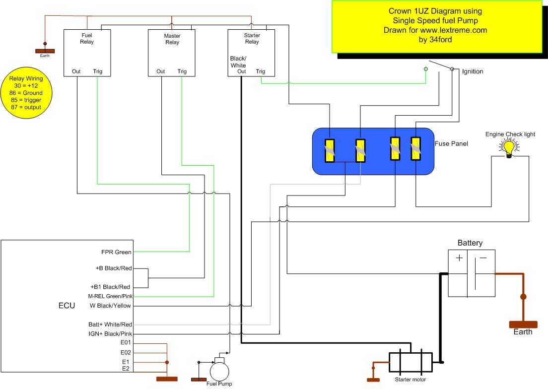
To wire the ECU with a single speed fuel pump make the following changes:
- Use only 3 relays.
- Terminate the Black/White (starter output to fuel pump power relay) wire at ECU plug.
- Terminate Green/Red (Fuel pump power relay) wire at the ECU.
- Do not fit the relay titled “hi-speed fuel pump”
- Run the Green (fuel pump speed control output) to the “Fuel pump” relay and connect it to the trigger terminal.
- Omit the fuel speed resister.
- Take the output from the Fuel pump relay direct to your fuel pump.
How Should it all Look?
The photograph below shows an installation that is easy to follow and took around 3 hours to assemble on the kitchen table.
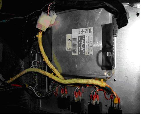
The in-car wiring took another couple of hours.
The neater it is the better chance you have of it being done correctly and it will be much easier to trouble shoot.
In the photo you will notice the two plugs to the engine loom are out as I have the ECU folded down for access. I could mount it upside down and the plugs would reach.
Notice the Relays lined up neatly on the alloy plate beside them. Plus the looms are neat and run in a logical order.
One improvement that could be made is to put some insulation along the panel below the relay terminals. To ensure no short circuits occur.
Below is a schematic of what we have described above. The schematic was drawn by 34Ford in Visio.
Single Speed Fuel Pump Diagram http://lextreme.com/article/1UZSingleSpeedFuelpump.jpg
Dual Speed Fuel Pump Diagram http://lextreme.com/article/1UZDualSpeedFuelpump.jpg
You didn’t specify the type of Toyota Crown Majesta e.g. like frame # UZS- 171 and the ECU part #like 89661-3A-590 I have to use these number for compatibility for my swap 1997 Hilux project using Toyota Crown Majesta 1UZ-FE and A650E transmission
Truly oralie